THE PROJECT
Force-4 developed a battery charging system for medical devices to charge them to the designated state of charge and hold them at that state until the device is removed from the system to proceed to the next manufacturing process step.
THE CHALLENGE
A device used in diabetes management requires a designated state of charge to proceed to the next step in the manufacturing process. The battery charging station is used in a medical product manufacturing facility as part of a manufacturing line. The specifications for the medical device battery charging system include:
- Charge a cell phone-based product to a specified percent charge requirement
- Charge and monitor 72 phones simultaneously and asynchronously
- Incorporate system health monitoring
- Align software development with client software development language specifications and development style
- Design system usability based completely on visual indicators and a touch screen interface
- Incorporate light emitting diodes (LEDs) to enhance operator visuals of charging state and align indicators with the software visuals
Software Requirements
The machine documentation included the following:
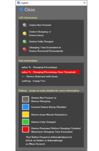
Figure 1. Display Indicator Legend
- User Requirements Specification (URS)
- Functional Requirements Specification (FRS)
- Functional Design Specification (FDS)
- User Manual (UM)
- Factory Acceptance Test protocol (FAT)
- Factory Acceptance Report (FAR)
The system communicates with the medical device to determine the actual battery charge state as reported by the device’s charge controller. It also monitors the electrical current draw of the medical device during charging. The system uses three streams of information for charging:
- Data Acquisition Stream
- Android Debug Bridge (ADB) Stream
- Charging Hub Stream
The operator interface is completely touch screen driven with display indicators matching physical LED charging status indicators at the physical device location. Figure 1 shows the display indicator legend.
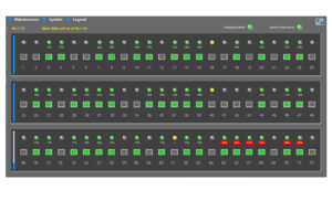
Figure 2. Battery Charging System
As shown in Figure 2, the indicators show the state of charge for any device in the medical battery charging station and provide additional information for each medical device in a specified charging slot, including;
- Device Identification Number
- Percent Charge
- Time Device Charging
- Current Draw of the Device
- Charging Port Voltage
If a device is removed from the cabinet prior to charging to the designated level, the system will alert the operator and require an override to continue using the associated charging port. The system notifies the operator if a device enters the charging system in an overcharged state. The software monitors the cabinet’s health and will shut the medical charging system down automatically if necessary. A button on the cabinet also allows the operator to completely disable charging in the cabinet if necessary.
The software includes a system maintenance window, as shown in Figure 3. When the window is opened, the battery charging software stops charging devices, and all charging slots are deactivated in anticipation of testing the LEDs on the panel. Once the maintenance window is closed, the software will restart, and charging will resume.
Modular Cabinet Design The mechanical cabinet structure shown in Figure 4, holds up to 72 devices as they are charging.
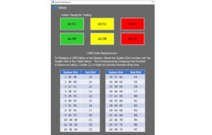
Figure 3. System Maintenance Screen
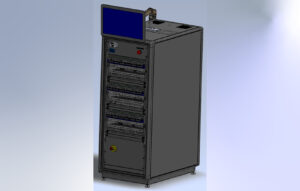
Figure 4. Cabinet Design
The charging station is designed with standalone 19” modular racks that hold 24 devices, as shown in Figure 5. Each assembly is duplicated three times in a cabinet to create the full charging station. This design provides the flexibility to build future systems that are smaller or larger in capacity.
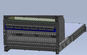
Figure 5. 24-Device Modular Rack
The cabinet design incorporates four thermocouples for measuring the temperature of each 24-device charging module assembly: one for the cabinet instrumentation and a left, middle, and right-side module temperature. The design also incorporates monitoring of power to the interconnect hub and each charging hub.
SUCCESS!
The Force-4 team delivered an innovative modular design for charging medical devices as part of a medical product manufacturing process. Whether your project is schedule-related or technical-driven, our team is the fastest path to meeting a product development need bringing together physics-based understanding with agile design, manufacturing, software development, and project management services to develop validated hardware and software solutions rapidly. It’s an approach worth considering for your next project!
At Force-4, Smart Ideas For A Smart World, we are a force for innovation because we envision and translate brilliant ideas into highly experiential and efficient products. Our expert team of strategists, industrial designers, and engineers unlock new ideas while navigating difficult technical challenges to take your product to market faster.
AUTHORS

- Clint Haynes, founder of the Cincinnati office of Stress Engineering Services, has steadily grown the Cincinnati practice area while introducing breakthrough capabilities. He has a specialized focus on areas of medical, outdoor, and product innovation.
- Mike Johnson, Principal, has more than 30 years of innovation in product development, design control, new product transfers, and short-run manufacturing.
Ref: C004-MD-Battery Charging Station for Large-Scale Medical Device Manufacturers
Keep in touch with us.
Sign up for our newsletter.